Combine Castings, Forgings, Bar Stock, and Stampings
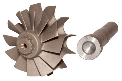
Cast turbocharger impeller and shaft, a popular friction welding application ready to be joined
Design Choices
A design engineer planning to fabricate unique part shapes has several choices in metalworking industries.
- Parts can be cut from solid billet or bar stock using machine tools.
- Castings can be made in a finished shape ready to use in many cases.
- Forgings can be made in other cases. Usually, these parts have simpler contours and require greater strength than castings.
- Sheet metal can be stamped into simple forms.
Breaking Down Complexity
What if the part is too complex to fit one casting mold, forging die, or to cut from one piece of bar stock? Complexity leads to joining two or more sub-components that come from one of these sources. This leads to making another choice on how to bond multiple pieces. If strength is a requirement, the options narrow.
Joining choices lead to compromise, primarily around measurements of strength. If the designer went to great lengths to create the strongest possible sub-component, adding a “weak-link” joint to the configuration might defeat project objectives.
No Compromise on Strength
Friction Welding offers a complementary solution to working with primary sub-component fabrication methods. A proper friction welded joint will be equal to or stronger than the parent material. The weld zone consists of a molecular fusion of the joined sub-components.
In the cross-section view below, we can see two forged carbon steel flanges that were bonded together in the friction welding process. The material is fused together into a continuous solid through the weld zone with all the strength of the parent material. The weld zone is non-porous and free from contamination.
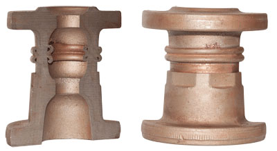
Two forgings bonded with friction welding (cross-section left, exterior right)
In the lower image, we see a detailed, machined shaft bonded with friction welding to a bell shape stamping. The part is ready to use as a transmission shift lever upon completion of the weld.
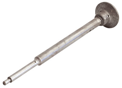
Machined steel tube bonded to steel stamping
You can see other ideas on how to meet component joining requirements in this gallery.
What is the most unusual part configuration that you have designed? Did you make it by joining sub-components?