Destructive Testing
Destructive Weld Testing involves the physical destruction of the friction welded components. A variety of testing methods can be employed to evaluate the weld’s characteristics. We perform these tests on all prototype welds per customer specifications.
Sampling inspections of production welds are performed to:
- Qualify weld performance
- Troubleshoot using failure analysis
- Research inspection processes to improve or validate current testing methods
Cross-section examination of the weld quality
- Using a macro etch test (and depending on the base material(s) joined in the weld), a mild acid mixture is applied to the cross-section surface.
- The resultant etching provides an excellent study of the internal structure of the weld, which is also helpful in detecting welding problems.

Closeup of friction weld zone
Bend Test in Action

Identify Integrity Issues
- Depth of Penetration
- Lack of Fusion
- Inadequate Root Penetration
- Internal Porosity
- Cracking or Inclusions
Additional tests may be applied to validate ductility, soundness of welded joints, tensile strength or any presence of slag inclusions or weld quality discontinuities within the entire length of the weld.
Depending on the characteristics requiring inspection, we use various destructive test methods for friction welds:
- Bend Tests: free bend, guided bend, longitudinal bend, transverse bend
- Etch Test
- Hardness Tests: Brinell hardness, Rockwell hardness
- Impact Test
- Nick-break Test
- Tensile Test
- Torque Test

Threaded Rod Inspection

Cross Sectioned Tube
Non-Destructive Weld Quality Testing
Ultrasonic inspection is used regularly to ensure weld integrity. This test is performed per customer specifications.

Non-destructive testing also involves inspection of welded components by subjecting them to the required service conditions to determine suitability. These tests are designed to reveal defects that may impair service performance. They will not break or alter the structure or appearance of the friction welded piece.

Friction Welding Video
Nondestructive Testing
Testing Friction Welding for Strength
Weld Parameters Developed for Reliability. Strength Equal or Greater Than Parent Material on Each Part.
Nitride hardened steel piston rod broken outside the friction weld zone. The indent near the break is the result of force from the press.

Thin-wall tube bonded to a solid base. This shows a section cut and bend test. The friction weld zone is unaffected.

This hollow shaft is friction welded to a solid piston. The section cut was tested by bending force. The parent material deflected before any effect reached the friction weld zone.
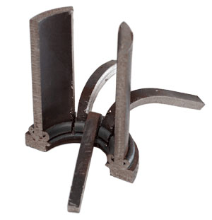
This test shows a thin-wall tube section cut into strips that are bent down into “petals”.

This bend test, of a shaft friction welded to a forged ring, demonstrates the incredible strength of the friction welding process.

This heavy-wall tube bonded to a solid base gave way before the friction weld did in this bending test.

A Nitride hardened steel pin was friction welded to a steel mounting plate. This bend test shows that the plated pulled apart with no separation of the friction weld joint.

A forged clevis was friction welded to a hardened, chrome-plated hydraulic piston rod. The bend test shows that the rod broke in the testing press with no failure of the weld zone.

This Class 8 trailer axle is made from heavy-wall tube friction welded to a forged spindle. This cut section was tested in a bending press. You can see that the tube gave way under force before any damage occurred in the friction weld zone.

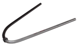
This threaded rod is friction welded to a cast cam. The bend test shows that the friction weld zone is stronger than the parent material.

OEM manufacturers require specific strength testing to assure that part performance complies with design. This valve stem was strength tested with a tensile pull, and it broke outside the friction welded joint where the shaft meets the disc. The tensile test shows that the friction welded bond is stronger than the parent material.
NOTE: This finished sample also illustrates that the friction weld zone can be machined like solid parent material.

As in the other “petal” bend tests on this page, this sample shows the friction weld bonded joint between a thin-walled tube and a solid cap is successful.

Here heat-treat hardened 8620 steel is bonded to stainless steel. The hollow stainless tube was cut for a “petal test”. The friction weld parameter is proven successful in this test example.

Another bend test, another win for friction welding.
This 1/8” diameter steel bar is comprised of one-half Nitride hardened steel joined to another half in untreated mild steel. You can see that the friction weld is stronger than either parent material side.