Friction Welding is a “solid-state joint process that produces coalescence of materials under compressive force contact of workpieces rotating or moving relative to one another to produce heat and to plastically displace material from the faying surfaces.”*
Used in the United States and Europe for more than 50 years, friction welding has been a well-kept secret. Sometimes it is referred to as spin weld or spin welding, because one part is rotated in process. As customers learn and understand the process, benefits become clear.
Reduce material consumption and shorten machine cycle time
The ability to create near-net shape blanks offers manufacturers an opportunity to reduce material consumption and shorten machining cycle time. Joining dissimilar metals like stainless steel alloys to other metals provides unique design flexibility.
Friction Welding Methods
Computer controlled Direct-Drive Rotary Friction Welding: provides continuous speed control through the cycle, and stops according to a computer parameter developed specific to the part.
Inertia Friction Welding: this uses part rotation under pressure to heat the faying surfaces.
- This uses a flywheel to generate the rotational momentum in the part-holding chuck.
- The flywheel-driven chuck spins until it stops when the weld zone seizes. This inertia method is also sometimes described by the colloquial term, spin weld.
* The Friction Welding Process was formally defined by the AWS on Oct 15, 2008, in the Recommended Practices AWS C6.1 for the Welding Industry.

Is the weld process computer controlled for repeatability and quality assurance?
Yes. Hand-set manual controls can introduce variables into the process that prevent repeatability from lot to lot over time.
Why AFW? Learn MoreLearn More:
Machine Set Up
- Parts are loaded into the friction welding equipment.
- Experienced operators set up the machine for each job to control the 3-step process with a series of parameters unique to each job: Rotational Speed, Axial Force, and Length. You can see images of friction welding’s three stages in the photos below.
- After the three parameters are established, they’re recorded and stored for use throughout the entire project.
Using this quality approach ensures repeatable consistency for each additional weld produced on the machine. The results are represented visually on the Playback Graph shown below the three steps.
Stage 1
One component is positioned in a stationary clamp. The second part is positioned in the rotating spindle, which is then brought up to a pre-defined rotational speed (blue line on graph). At the right moment, pre-defined axial force (red line on graph) is applied.
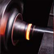
Stage 2
These conditions are maintained for a predetermined time. The second step of pressure is applied (second step on red line on the graph at about 1 seconds in this example) until the desired temperatures and material conditions exist. It’s during this stage that the two materials are plasticized (become malleable). The green line signifies measurement of “length loss” and triggers the stopping point when the part reaches planned Overall Length.

Stage 3
Rotational speed is stopped. Then increased axial force (third step in the red line at 9.5 seconds) is applied to create “forge pressure” for another predetermined time – completing the weld. This provides molecular bonding and grain refinement through the weld zone.

Playback Graph
Shows the record of weld parameters applied in the Stage 1-2-3 images above.

Video of Friction Welding Process in Action
High Precision Friction Welding (HPFW)
High Precision Friction Welding (HPFW), also referred to Smart Rotary Friction Welding (SRFW) is a subgroup of friction welding focused on the ability to achieve the highest manufacturing accuracy in the production of a component’s parts.* This subset is generally reserved for component parts that are required to satisfy the highest demands for position and accuracy.
The keys to a high factor of reproducibility using this method are:
- The utilization of feedback control systems
- Precision clamping devices
- Pre and post machining on the welder itself utilizing a lathe operation
The HPFW method is highly recommended if the failure of the welded components would make the final product dangerous. Certainly there are applications where a possible weld failure has minimal risk. If no risk of failure is imperative, HPFW is the best option.

For reference, ISO 15620 spec refers to the Category A guideline for quality assurance. One of the main goals in using an HPFW model is to gain reliable and predictable outcomes to ensure your product performs in a known way prior to field use. AFW proudly offers this next generation of fabrication that utilizes the proven solid-state joining process we have been leveraging for 30 plus years.